A deployment diagram allows you to illustrate how containers in the static model are mapped to infrastructure. This deployment diagram is based upon a UML deployment diagram, although simplified slightly to show the mapping between containers and deployment nodes. A deployment node is something like physical infrastructure (e.g. a physical server or device), virtualised infrastructure (e.g. IaaS, PaaS, a virtual machine), containerised infrastructure (e.g. a Docker container), an execution environment (e.g. a database server, Java EE web/application server, Microsoft IIS), etc. Deployment nodes can be nested.
Example
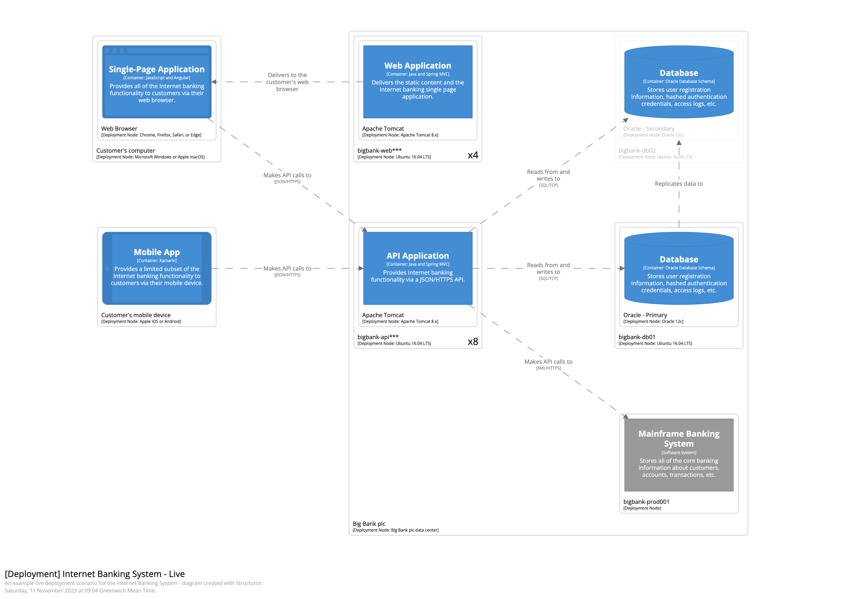
As an example, a Deployment diagram for the live environment of a simplified, fictional Internet Banking System might look something like this. In summary, it shows the deployment of the Web Application and the Database, with a secondary Database being used for failover purposes.
See InternetBankingSystem.java for the code, and https://structurizr.com/share/36141/diagrams#LiveDeployment for the diagram.